
Transfer moulding of elastomers - precise production of technical moulded rubber parts
1. what is transfer moulding?
Transfer moulding is a process for the production of elastomer moulded parts in which preheated rubber material is pressed under pressure from a separate transfer chamber via channels into closed mould cavities and vulcanised there under the influence of temperature.
The process belongs to the group of compression moulding processes and is a further development of compression moulding. It enables more precise material distribution, reduces air pockets and is particularly suitable for complex geometries and for rubber-metal, rubber-plastic and other elastomer composite parts.
Transfer moulding is typically used for technically demanding components with medium quantities and offers greater process stability than pure compression moulding, but lower levels of automation than elastomer injection moulding.
Transfer moulding is the right choice for rubber-to-metal elements, rubber-to-plastic elements and rubber-to-fabric elements, which are often produced in small to medium quantities. It impresses with dimensional accuracy, reproducibility, good scalability and less manual effort than compression moulding, with slightly higher initial tool costs.
The common alternatives to transfer moulding are the closely related compression moulding and injection moulding. Transfer moulding is also seen as a further development or special form of compression moulding, as it differs from compression moulding mainly in that the raw material is introduced into a separate transfer chamber instead of directly into the cavities. Although this makes the moulds relatively more complex, the efficiency of production increases significantly.
2. structure and function of transfer moulds
As a shaper and reaction chamber for vulcanisation, the mould performs several critical functions: It guides, moulds, transfers pressure and temperature - and ensures the reliable production of even complex moulded rubber parts.
Transfer moulding tools are generally made from high-strength, temperature and pressure-resistant tool steel. Unhardened or hardened tool steels with good thermal conductivity are often used. The thermal conductivity of the material is just as important as its hardness, as this is the only way to realise uniform temperature profiles and replicable processes. In contrast to compression moulding, aluminium tools are rarely used because, in addition to the higher requirements for dimensional accuracy, the use of the additional piston element means that longer service lives must be achieved, as transfer moulding is generally used for higher quantities than compression moulding. Aluminium or copper alloys are often used as heat carriers and conductors for the heating and cooling plates, supplemented by electric or steam-heated systems.
Structure of the tool
- Piston (plate)A piston that presses the primary material from the transfer chamber into the cavities. The piston is part of the mould and not the press itself. Designs with several pistons and transfer chambers are also common.
- Upper and lower mould (tool halves)Contains the transfer chamber and the negatives of the moulded part.
- Heating and cooling platesHeating plates : Heat the mould halves to the desired vulcanisation temperature (usually 160-200 °C) and are thermally insulated from the pressure plates. Heating elements or cooling channels are often integrated directly into the mould halves instead of separate plates.
The piston can have a classic rotationally symmetrical design, but in practice it often has other geometries. A thin rectangular metal plate that rests on the rubber disc is often used as the piston shape, particularly in the case of plate-shaped raw materials.
Structure of the mould halves
- Transfer chamber: Used to insert the rubber raw material, usually in strips or sheets, and is located above or to the side of the cavities.
- Duct or distribution system: guides the raw material into the cavities under pressure.
- Cavities (also mould cavities)Define the geometry and surface of the part to be produced as a negative mould.
- Ventilation ducts: Conducts trapped air and gases out of the mould.
- Centring and guide bushes: Ensure precise closing position and repeat accuracy.
- EjectorFacilitate the removal of components after opening the mould.
Even with a specified component geometry, tool design and production is not only a cost factor, but above all a quality-determining element of the overall process, e.g. through
- Canal systemThe dimensioning and positioning of the runner system has a central influence on the component quality by enabling uniform and complete filling of the cavities. The material yield and therefore the costs also depend, for example, on minimising the proportion of sprue.
- Mould divisionThe choice of parting line not only has an influence on the production process, e.g. the removability of the components or the effort required for deburring, but also on the quality of the components, e.g. due to changed flow paths.
- Geometry of the cavitiesThis must be precisely selected and manufactured, but does not necessarily correspond exactly to the component negative if, for example, shrinkage has to be taken into account.
- Surface quality of the cavitiesThe surface quality of the cavities is the key factor influencing the surface quality of the finished component. While milled mould surfaces are often sufficient for simple components, erosion is predominantly used as a manufacturing process, particularly for visible parts.
- Positioning of insertsIn the case of composite parts, the inserts, i.e. the non-rubber components, must be precisely fixed but also easy to insert. The type of positioning has a correspondingly large influence on process reliability and costs.
- Transfer moulding cold runner: The design of a cold runner has a significant influence on temperature control, flow behaviour and material utilisation. Efficient cooling of the transfer unit prevents unwanted vulcanisation and allows the material to be reused, which ensures consistent component quality and fewer rejects.
Particularly with complex geometries or large quantities, it can be useful to adapt the component design for the production process, for example to avoid undercuts or to facilitate demoulding by means of demoulding chamfers.
3. the transfer moulding process - step-by-step procedure
The production process in transfer moulding follows a clearly defined, reproducible pattern. Despite its apparent simplicity, each step involves technical parameters that must be precisely coordinated in order to achieve consistent component quality while using resources economically.
Step-by-step process
- Inserting the rubber material
The raw material is usually inserted into the transfer chamber in the form of strips or discs. - Locking the tool halves
First, the mould halves (upper and lower mould) are force-fit closed using a hydraulic press with controlled closing force. A piston then presses the raw material with a defined force - typically between 30 and 200 tonnes - through a channel system into the closed cavities. The flow path, viscosity and venting behaviour must be precisely coordinated to ensure uniform and faultless filling. - Temperature control and vulcanisation
The mould halves are heated to 120 to 220 °C via separate heating plates or integrated heating cartridges, steam or oil depending on the material and cross-linking system - depending on the material. The dwell time in the mould, i.e. the vulcanisation time, depends on the material:
- Material and cross-linking system (peroxide cross-linking, sulphur cross-linking, etc.)
- Wall thickness of the component
- Mould design (mass ratios, thermal inertia)
Typical cycle times are between 2 and 15 minutes, However, this can be significantly higher for thick-walled or multi-layered parts. Cross-linking turns the rubber into a rubber/elastomer.
- Opening, demoulding and post-processing
Once vulcanisation is complete, the mould is opened. Demoulding is carried out manually, mechanically via ejectors or using compressed air. This is usually followed by Post Processing:
- Removal of burrs
- Mechanical, e.g. barrel finishing
- Thermal e.g. freeze deburring
- Manual, e.g. by scalpel, scissors, tear-off
- Visual inspection and, if necessary, dimensional check and hardness test
- Coating, e.g. talcum coating
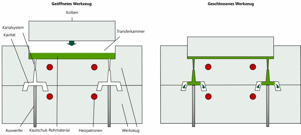
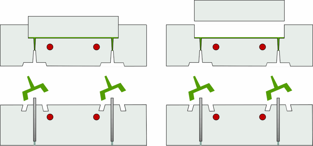
Figure 1: Schematic representation of transfer moulding before the plunger stroke (top left), during moulding (top right), when ejecting the finished product (bottom left) and lifting the plunger (bottom right)
4. critical process parameters - control of component quality
Three central physical process parameters directly influence the result:
- TemperatureToo low temperatures lead to under-vulcanisation (sticky surfaces, reduced strength, DVR, dimensional stability, etc.), too high temperatures lead to over-vulcanisation (embrittlement, dimensional distortion).
- PressureToo low pressure causes air pockets or filling errors, too high pressure can damage the mould or lead to increased burr formation.
- TimeThe holding time must be sufficient for complete cross-linking without unnecessarily extending the cycle time. Under-crosslinked parts are mechanically unstable and cannot be used.
These parameters have the following effects interdependentFor example, an increase in temperature can compensate for a shorter time, but only within the material-specific permissible range. Accordingly, a Precise process control with validated recipes and stored pressing cycles is essential, especially for quality-critical applications.
5. economic key figures in the compression moulding process
In addition to component quality, economic aspects are also decisive for the evaluation of a compression moulding process. Typical key figures are
- Cycle time [s or min]directly dependent on heating phase, vulcanisation time and demoulding
- Mould utilisation factor [%]Ratio of cavities to total mould area
- Reject rate [%]Defective parts per batch
- Material yield [%]Proportion of the raw material that remains in the good part
- Burr content [g/part]Indicator for material loss and reworking costs
- Set-up time [min/lot]Effort for mould change and start-up
The aim is to use process-stable parameter control and precise mould technology to High repeat accuracy with minimal rejects to realise.
6 Materials for transfer moulding: Which elastomers are suitable and why?
Similar to compression moulding, transfer moulding can also be used to process almost all elastomers. The only exceptions are thermoplastic elastomers (TPE) or elastomers with particularly short pot lives, which are processed using injection moulding.
Compared to compression moulding, flowability under pressure and resistance to shear stress play a more important role, as the raw material still has to be pressed into the cavities via the channel system before moulding. The elastomers commonly used for transfer moulding are nevertheless identical:
Elastomers for transfer moulding
- NR (natural rubber)
Good mechanical properties, high rebound resilience and abrasion resistance. Used in dynamic applications, such as vibration elements or dampers. - NBR (acrylonitrile butadiene rubber)
Resistant to oil, grease and fuel. Universally applicable in seals, diaphragms and hoses in hydraulic systems. - HNBR (Hydrogenated NBR)
Kombination aus chemischer Beständigkeit und hoher mechanischer Festigkeit. Eingesetzt in anspruchsvollen Dichtungs- und Lageranwendungen. - EPDM (ethylene propylene diene rubber)
Excellent resistance to weathering, ozone and ageing. Particularly suitable for outdoor, construction and automotive applications. - VMQ / FVMQ (silicone / fluorosilicone)
High thermal stability, flexibility at low temperatures, excellent insulating properties. Ideal for medical and food technology as well as applications with extreme temperature gradients. - CR (chloroprene rubber, e.g. B. Neoprene)
Flame retardant, resistant to ageing, good adhesion to metals - frequently used in rubber-metal bonds. - FKM (fluororubber)
High-temperature and chemical-resistant elastomer used primarily in demanding applications such as seals, hoses and O-rings in the automotive, chemical and aerospace industries.
Influence of material properties on the moulding process
The choice of material not only determines the properties of the end product, but also has a significant influence on the moulding process:
- Viscosity of the mixture influences the flow behaviour - highly viscous materials require higher closing forces.
- Reactivity of the cross-linking system (e.g. peroxide crosslinking vs. sulphur crosslinking) influences cycle time and temperature control.
- Thermal behaviour has an effect on demoulding and shrinkage.
The combination of material, moulded part geometry, tool design and process parameters must therefore be Systematically harmonised This is particularly important in regulated industries where validation and component approvals are based on exact material parameters.
Material selection as a strategic lever
The right choice of material is not only technically decisive, but also economically relevant. Factors such as material price per kg, reject rate, reworking costs and shelf life have a direct impact on unit costs and process stability. For this reason, material optimisation is often used in practice, for example through:
- Substitution of expensive fluoroelastomers with optimised HNBR or EPDM compounds
- Use of multi-component joints (hard/soft composite parts)
- Adaptation of the recipe to specific cavity geometries or sizes
7 When is transfer moulding the right choice?
Transfer moulding is just one of several established processes for manufacturing technical moulded rubber parts. The three most common discrete processes are compression moulding, transfer moulding and injection moulding. Each of these processes follows its own principles, requires specific moulds and offers different advantages depending on the component geometry, quantity, material properties and economic context. The most common continuous process, however, is extrusion.
Transfer and compression moulding are closely related. In contrast to transfer compression moulding, the rubber material is inserted directly into the cavities during compression moulding and pressed there.
In injection moulding, on the other hand, the material is plasticised and injected directly into the mould under high pressure. This makes it ideal for large quantities, but is associated with high mould costs and is only suitable for a limited range of elastomers.
Detailed technology comparison
| Criterion | Compression Molding | Transfer Molding | Injection moulding |
|---|---|---|---|
| Series size | Small to medium series | Centre series | Medium to large series |
| Variety of materials | Very high | High | Limited |
| Automation capability | Low | Medium | High |
| Tool costs | Low to medium | Medium to high | High |
| Cycle time | Medium to long | Medium | Short |
| Composite part production | Well suited | Well suited | Limited suitability |
Advantages and disadvantages of transfer compression moulding at a glance
Advantages:
- Good dimensional accuracy and reproducibility, even with complex components
- Wide range of materials can be processed
- Well suited for thick-walled components
- Very suitable for rubber composite parts (e.g. rubber-metal connections)
- Low burr content due to controlled filling of closed cavities
- Flexible use, ideal for medium series and wide product variants
Disadvantages and limitations:
- Longer cycle times than injection moulding with comparable component complexity
- Material losses due to sprue in the runner system and remaining raw material residues in the transfer chamber
- Manual effort during insertion / removal, if not automated
8. conclusion transfer moulding
Transfer moulding is a standard process in the manufacture of moulded rubber parts and rubber composite parts. It is the right strategic choice especially for:
- Series sizes of approx. 1,000 to 100,000 units per year, where the ratio of mould costs to part price remains economical,
- rubber composite parts, such as rubber-metal compounds, and
- Materials that are not suitable or only suitable to a limited extent for injection moulding.
- Small parts with a high number of cavities
Transfer moulding impresses with its dimensional accuracy, reproducibility and better scalability, as it requires less manual effort than compression moulding but has slightly higher initial tool costs.