

How are plastic parts deburred and by what methods?
1. Types of deburring
The removal of flash can be done manually, thermomechanically, by friction, or by tools. When rubber is to be deflashed, there are fundamentally four industrial methods to choose from. The right choice is not just a question of price for the respective method, but rather a combination of quantity, geometry, and material. Most rubber moulded parts have to be deflashed after vulcanisation. Below, we compare four methods with their respective operating principles, their strengths and their limitations.
Manual deburring (cutter knives, special shears, punching tools)
In manual deburring, an employee removes the burr with a cutter knife, special shears, cutting templates, or simple fixtures. The process requires no investment in plant technology, can be used immediately, and is also suitable for geometries that are difficult to handle with other automated processes. Furthermore, all parts are visually inspected in the manual process.
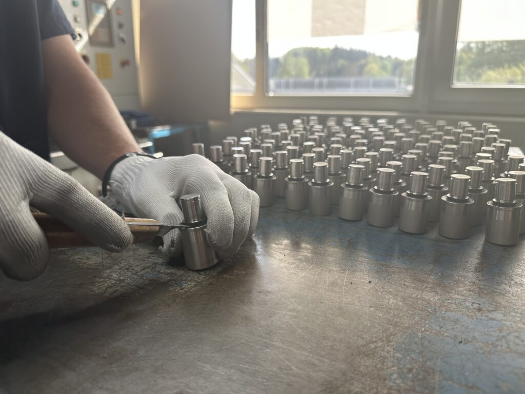
Figure 1: GUME employees manually deburring a Metal composite part.
StrengthsHigh flexibility with changing parts, immediate visual inspection, and use with large or form-sensitive components.
Bordershigh personnel costs, significant variation in work results and thus limited reproducibility. For production volumes above a few thousand parts per year, the economic viability increasingly shifts in favour of automated processes.
Cryogenic deflashing (tumbler and deflashing treatment with liquid nitrogen)
Cryogenic deflashing is a thermo-mechanical process in which rubber moulded parts are cooled to temperatures between -20°C and -150°C using liquid nitrogen, causing thin flash lips to fall below their glass transition temperature and fracture brittlely. There are two process variants: In drum deflashing, the components rotate in a cooled drum, whereby the embrittled flash breaks off through part-to-part friction; in blast deflashing, a blast medium – typically polycarbonate granules with grain sizes of 0.3 to 0.8 mm – additionally blasts the embrittled flash lips and removes them specifically.
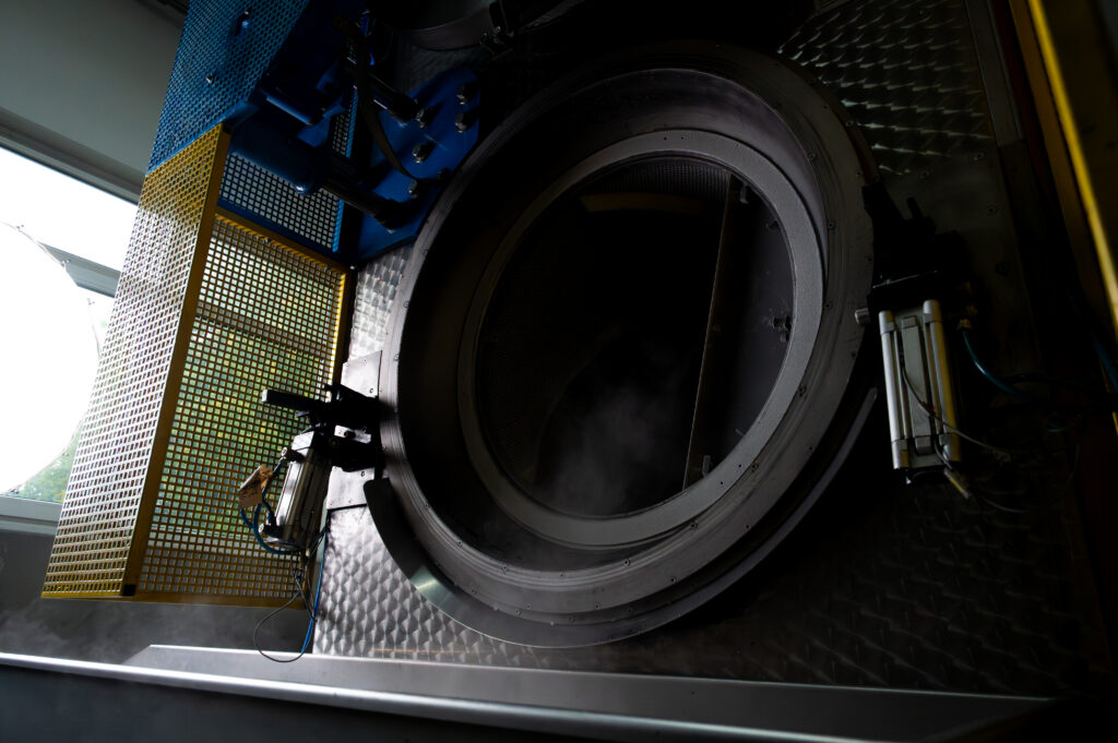
Figure 2: Cryogenic deburring machine from GUME production.
The process outcome is primarily determined by the ratio of component cross-section and dwell time. With typical cycle times of 2 to 10 minutes and the low thermal conductivity of elastomers (0.15 to 0.30 W/(m·K)), the thin flash initially cools completely below its glass transition temperature, while thick-walled component areas retain an elastic core zone. The embrittlement depth is therefore dependent on the component cross-section and allows delicate flashes (typically 0.05 to 0.2 mm thick) to be selectively brittle-fractured without mechanically compromising the more massive component body. In the case of thin-walled geometries with a wall thickness of less than approximately 1.0 mm, such as Membranes, Bellows and lip seals, the entire component is cooled. Shorter dwell times and gentler blasting parameters are then required to avoid component breakage. The choice of process temperature depends on the glass transition temperature of the rubber compound: for FKM, approx. -30°C, for VMQ, up to -120°C. During cryogenic deflashing, the rubber flash is not completely removed, but a small residual flash remains – depending on dwell time and economic viability.
The material properties of the component remain unchanged, as the low temperature acts reversibly and the rubber or. Silicone moulding returns to the rubber-elastic state after thawing without structural change.
The strengths of cryogenic deflashing are: High reproducibility with documented system parameters, geometry-independent internal and external machining in one cycle, suitability for undercuts and intricate contours, no colour, geometric or mechanical change to the component.
Borders Investment in plant technology or external deburring required, nitrogen consumption as a variable cost item, limited suitability for components above typical plant capacities of 100 litres drum volume, as well as for thin-walled geometries and composite parts with adhesive bonds or heat-sensitive inserts that are mechanically stressed by temperature changes.
Drum and vibratory deburring without cryogenic treatment
In classic drum or vibration deburring without nitrogen, components are moved at room temperature in a drum or vibrating container. This is achieved either purely by friction against each other or with grinding media and additives. The process is inexpensive to acquire and operate, and is particularly suitable for robust geometries.
Strengthslow unit costs, simple plant technology, high throughput for large series.
Bordersless precise result than with cryogenic processing, possible edge rounding and surface polishing as a side effect, limited suitability for thin-walled or delicate parts. Compared to cryogenic deburring, dimensional accuracy suffers significantly more because the material removal is not limited to the burr but also affects the edge area of the component.
Stamping and cutting edge deburring as a tool-dependent separation point
The stamping or cutting burr is either implemented directly in the die as a so-called „“Tear-Trim" or implemented as a downstream die-cutting process. During the deburring process in the tool, the burr is torn off at a defined breaking point when the tool is opened. In manual or automated downstream stamping, a separate device is used onto which the rubber moulded part is placed and guided through the stamping punch.
Strengths: process-integrated, very high reproducibility, no additional logistical steps, lowest unit costs in large-scale production. Limitations: high initial outlay for tool design, limited geometric freedom (the parting line must be incorporated into the design), tool wear at the parting edge over the service life. The effort only becomes economically viable from larger batch sizes – but then significantly so.
Stamping and edge deburring as an operation-bound or downstream separation point
Stamping and parting off comprise two technically disparate processes: tool-bound separation in Form tool and the downstream punching in a separate device.
In tool-bound separation (also known as tear trim), the toolmaker constructs a deliberately weakened material bridge between the component contour and the flash (sometimes with a thickened tear-off edge), which serves as a defined breaking point. When the tool is opened or when demoulding, the flash tears off at this bridge. The component body remains with a sharp-edged tear-off edge. The prerequisites for this process are precise parting line guidance, high-strength tool steel in the area of the tear-off edge, and a rubber compound with lower tear propagation resistance.
At the downstream dies The vulcanised component is placed onto a contour-matching die after demoulding. A stamping punch then separates the flash manually or automatically in a separate stroke. The process decouples deflashing from the vulcanisation cycle and therefore requires less tool complexity. The use of an external device is significantly simpler than integrating a tear-trim geometry into the mould. However, this creates an additional logistics and handling step.
Strengths High reproducibility through machine-guided separation, defined cut or tear edge without operator influence, very low unit costs in large-scale production.
Borders increased initial outlay for tool or fixture design, limited geometric freedom, as the parting line must be incorporated constructively and placed outside functionally relevant areas, tool wear on the parting or cutting edge over the service life. The economic threshold depends on the chosen variant: Subsequent punching is already worthwhile in smaller series, tear-trim only at volumes that amortise the higher tooling costs.
2. Which deburring method suits which elastomer moulded part? Decision-making aid for deburring rubber moulded parts
The right choice depends on four variables: quantity, component size, geometry, and material. Below is a practical guide.
Selection by Quantity: Prototype, Small Batch, Medium Batch and Large Batch
For prototypes and very small series (1 to approx. 500 pieces), manual deburring is usually the most economical option, as the investment in machinery or the cost of outsourced deburring is out of proportion to the quantity. For small series (500 to 5,000 pieces), cryogenic deburring is often worthwhile, as its reproducibility and quality are superior to manual processing, and the logistical effort can be limited to a few batches.
In the mid-range series sector (5,000 to 50,000 units), cryogenic deburring is generally becoming the standard. For large series of around 50,000 units or more per year, tool-bound stamping or cutting solutions are economically viable, provided that the component geometry and tool concept allow for it. Drum and vibratory deburring remain a cost-effective option for robust components in various series sizes with moderate tolerance requirements.
Selection by component size and geometry
Components with undercuts, thin lips, or complex internal contours are the domain of cryogenic deburring. Embrittlement captures all burr locations regardless of their position and accessibility.
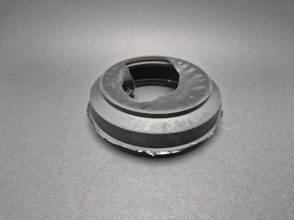
Figure 3: Rubber moulded part before cryogenic deflashing
The burr thickness that can be economically removed is typically in the range of 0.15 mm – and even more with favourable component design. Particularly thin functional geometries, such as thin button covers or membrane domes, can also be damaged by cryogenic deburring. Cryogenic deburring is also unsuitable for large-volume components like crane buffers or large seals. In these cases, manual deburring predominates – possibly in combination with fixtures or cutting templates for repeatability. Medium-sized standard parts with a simple parting line and no undercuts are the typical candidates for tool-bound solutions.
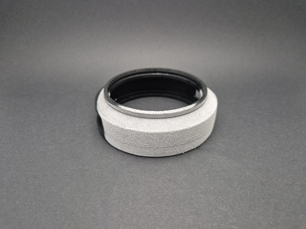
Figure 4: Rubber moulding after cryogenic deburring
Material selection: Tg behaviour and hardness
Two material parameters govern the choice of process: the glass transition temperature (Tg) and the Shore hardness. The Tg determines whether and at what processing temperature the flash becomes brittle. Hardness dictates the fracture behaviour under a flash or friction impulse.
Cryogenic deflashing requires a sufficient difference between the minimum plant temperature (typically −150 °C) and the Tg of the compound. The greater the difference, the more reproducible the fracture behaviour. Within the same material family, Tg values can deviate recipe-dependent by up to 20 K. Silicone also exhibit a second thermal transition in the form of partial crystallisation above the Tg, which causes thin web lips to break brittlely and is more economical due to lower nitrogen consumption.
Shore hardness influences the fracture behaviour under blast or friction impulse. Even when embrittled, very soft compounds tend to exhibit elastic deformation rather than a defined fracture. For these materials, manual or tool-assisted deburring is more robust. Very hard compounds are prone to cracking on the component contour with aggressive blasting parameters. The specific process limit depends on the compound, geometry and blasting parameters and is tested in the initial sample trial.
Composite and multi-component parts. Thermal stresses between materials with different coefficients of thermal expansion stress bonding surfaces, heat-sensitive adhesives and thermoplastic inserts. In the case of rubber-metal bonds or critical composite parts, the choice of process may shift in favour of manual or tool-assisted separation.
3. When is cryogenic deburring more advantageous than manual deburring?
Cryogenic deflashing is worthwhile as soon as reproducibility, unit costs or geometry are unfavourable compared to manual deflashing. The economic threshold is often reached with just a few thousand parts per year, provided the flash formation is stable across the tool and process.
Economic threshold and typical unit costs
In manual deburring, personnel costs dominate the calculation. Depending on the complexity of the component, an experienced operator typically manages between 100 and 600 parts per hour. In cryogenic deburring, machine hourly rates and nitrogen consumption are the cost drivers. However, the direct processing costs per part decrease significantly as soon as batch sizes of a few hundred parts per cycle are reached.
Even with medium batch sizes, the cryogenic solution often proves cost-effective, and the variability of the result is significantly lower than with manual deburring. If tolerances, visible surfaces, or documented process reliability are required, documented and reproducible system parameters can also be used.
Material conservation, reproducibility and limits of burr thickness
One significant advantage of cryogenic deburring is that the material properties of the component remain unchanged, as the low temperature only affects the surface down to the root of the burr and the core of the component is not cooled through. Colour, geometrical or mechanical changes practically do not occur. However, rubber dust resulting from the separation of the burr can adhere to the surface after cryogenic deburring. Therefore, cryogenically deburred elastomer parts are often washed afterwards.
Thick burrs above approximately 0.2 mm, for large-volume components that exceed plant capacity, and for composite parts with adhesive bonds or heat-sensitive inserts that are stressed by temperature changes, are not suitable. In these cases, manual deburring remains the better option, possibly supplemented by locally applied grinding or cutting tools.
4. Impact of deburring rubber moulded parts on the component outcome
Deburring also alters the component, even when a material-friendly process is chosen. Three aspects deserve particular attention: the remaining burr after deburring, the surface quality on visible and sealing surfaces, and the question of what unintended damage or material changes might occur.
Surface finish and dimensional accuracy after deburring
No deburring process produces a perfectly burr-free edge. With manual deburring, a slight residual burr remains, depending on the operative and the fixture. The result of cryogenic deburring depends on the dwell time, temperature, etc.
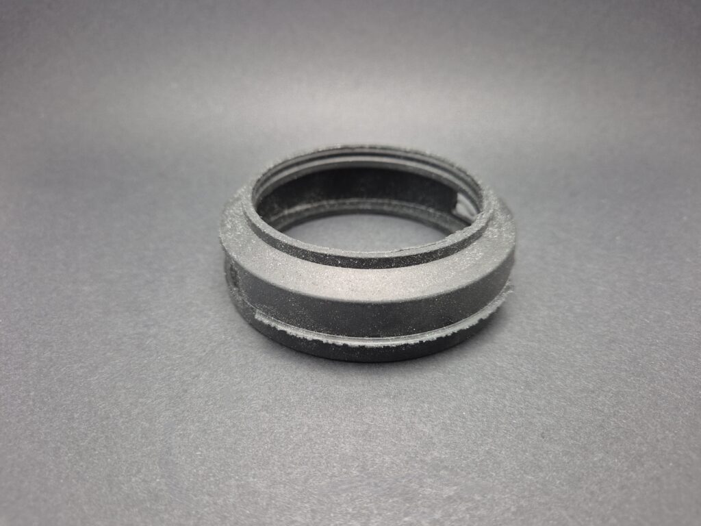
Figure 5: Representation of a rubber moulded part with distinct residual flash due to premature removal from the cryogenic deflasher
Through random irradiation with granules, freeze deburring produces an uneven finish with very little burr and areas with a higher occurrence of burr. Tumbler deburring at room temperature with abrasives not only removes the burr but also rounds off corners and edges.
Tool-mounted punching or cutting solutions produce virtually no burr when precisely designed – instead, they create a characteristic tear-off edge, which can be considered an advantage or a limitation depending on the component requirements. For sealing surfaces requiring micrometer precision, this tear-off edge is often too rough; for functionally neutral outer edges, however, it is unproblematic.
Surface quality for visible and sealing surfaces
Stricter requirements for visible surfaces influence the choice of process. Barrel deburring produces a uniform surface which is desirable in many cases. Cryogenic deburring practically does not alter the surface; the component texture of the tool is preserved. Manual deburring can leave scoring marks, the visibility of which depends on the care taken during the operation.
For sealing surfaces that require a defined contact pressure and a smooth finish, the transition from the component contour to flash removal is critical. A deliberately chosen offset of the parting line away from the sealing area avoids this problem. Here, tool design experience pays off twice. It reduces both flash formation and the effort required to restore a perfect sealing surface.
Potential damage and material changes
Defect removal can also lead to damage that renders the component unusable. Manual deburring carries the risk of cut notches, slipped blade guides, and cosmetic marks. Tumbling can cause material removal beyond the burr zone and edge rounding if cycle times are too long or the abrasive media are too aggressive. Cryogenic processes are particularly gentle, but if temperatures are too low or cycles too long, they can also cause component contours to break – especially with composite parts featuring rubber-metal transitions, which are subjected to mechanical stress due to differing thermal expansion.
Material changes occur practically only in thermal or energy-intensive processes. Within the four processes discussed here, such changes can be largely ruled out provided that process parameters are documented and run reproducibly.
5. Summary and Next Steps
The deburring of rubber moulded parts is part of the technical process chain with leverage on unit costs, component quality and process reliability. Three points summarise the most important findings of this contribution.
2) Corrosion is a result of tool, process, and compound and can be reduced by early-stage low-corrosion parting surfaces in the tool design.
2) There is no universal procedure. Manual deburring is dominant for small and large components, cryogenic deburring for delicate medium to large series, tumbling/vibratory deburring for robust components, and tool-bound punching/cutting deburring for large series with a structurally suitable parting line.
3) The choice of material and deburring method cannot be designed independently of each other. The glass transition temperature, hardness, and composite structure determine the suitable method. For special formulations, composite parts, or new compounds, an initial sample test with varying process parameters provides the best basis for decision-making.
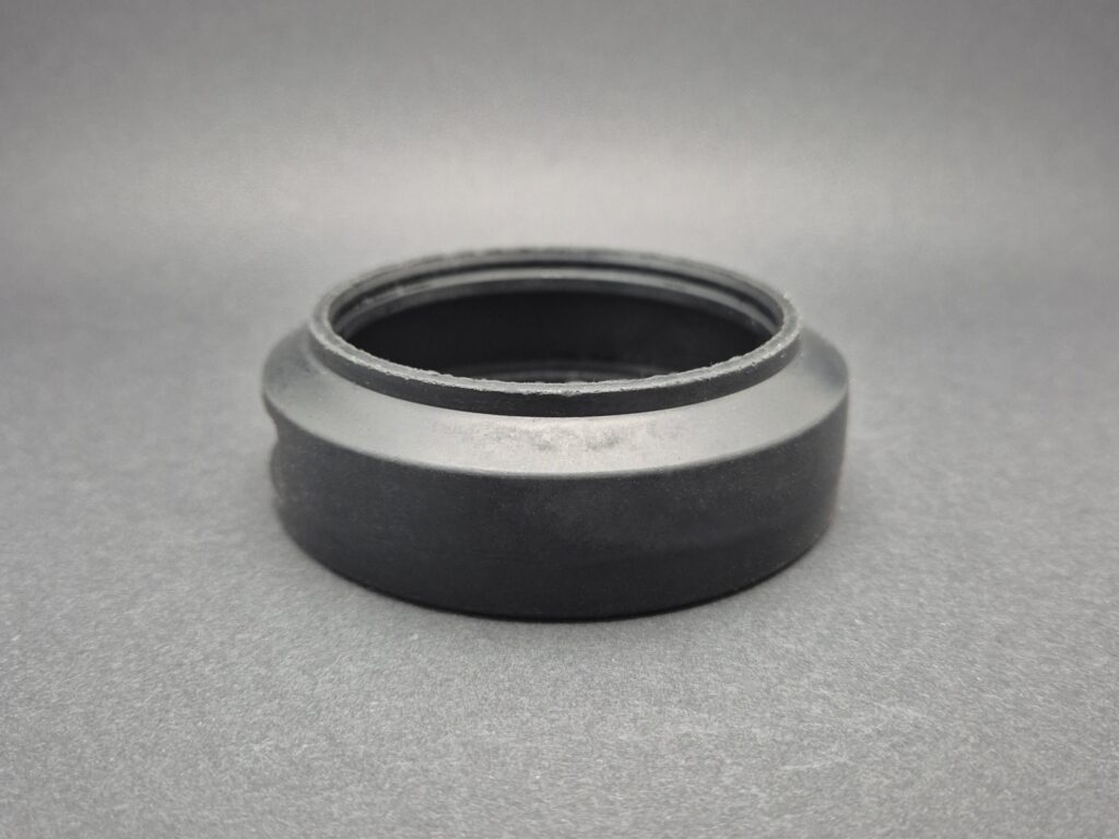
Figure 6: finished rubber part after cryogenic deflashing
Which process is best for your specific component depends on the quantity, geometry, material, and tolerance requirements. Send us your drawing and the planned quantity – we will review the tool design, material selection, and deburring process in a continuous workflow and get back to you with a technical recommendation and a quote. You will typically receive an initial assessment within two working days.
